A pipeline can be defined as a system of pipes for the transportation of fluids in liquid or gaseous phase, or a combination of both phases, between (but excluding) wellhead facilities, manifold stations, production plants, pressure boosting stations, processing plants or storage facilities. A pipeline extends from a pig trap to a pig trap (including the pig traps and associated pipework and valves), or, if no pig trap is fitted, to the first on plot isolation valve within the onshore plant as applicable.
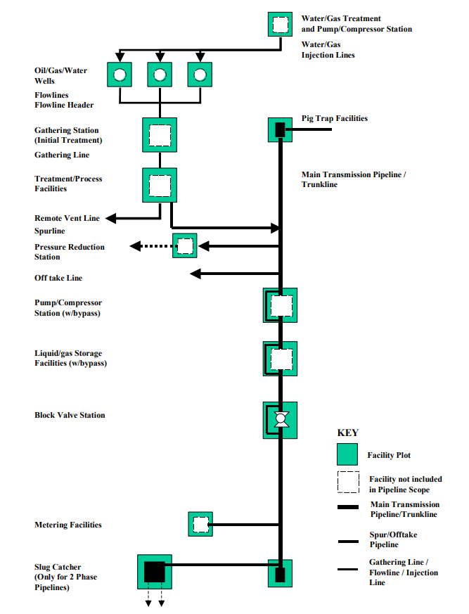
The following diagram shows a representation of pipeline scope between different onshore oil and gas facilities. As can be seen, pipelines connect different facilities together, but those facilities are not part of the pipeline engineering scope. Depending on the start and end points, we have different names/types of pipelines as follow:
- Trunkline: A main transmission pipeline connecting processing facilities and/or pump stations to which spur lines and off take lines may be connected.
- Spur line: A pipeline transporting fluid into a larger pipeline.
- Off-take line: A pipeline transporting fluid from a larger pipeline.
- Flowline: A pipeline transporting fluid hydrocarbons and/or other reservoir fluids between a wellhead and a gathering or treatment facility or vice versa.
- Header: A section of pipe or pipeline collecting or distributing fluids from several sources or destinations.
- Loading line: A pipeline between a storage facility and a sales facility, e.g. a single point mooring or product truck loading.
- Injection line: A pipeline transporting gas, water or other fluids for injection into a well or a group of wells.
- Inter-field pipeline: A pipeline between two processing facilities, transporting processed hydrocarbon or other reservoir fluids.
- Two-phase pipeline: Pipeline transporting fluids where the liquid phases and the gas phase are present at the pipeline’s pressure and temperature conditions.
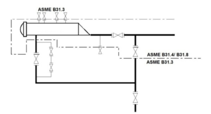
For the purpose of code break, it is assumed that the piping of facilities to which the pipeline/pig trap system is connected is designed in accordance with ASME B31.3. A pipeline extends from a pig trap to another and includes the pig traps and associated pipe work and valves. The delineation between the pipeline and the facility is the specification break between pipeline design code ASME B31.4/B31.8 and the station design code ASME B31.3. Where this is not the case e.g. at intermediate pig trap stations or where the pig trap ties into a slug catcher designed to ASME B31.8, the code break/delineation is not applicable.
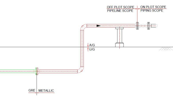
In case of GRE pipelines, the scope break between off plot and on plot should be as follow:
- The metallic section in off plot section shall be as per adjacent on-plot piping class, and the welding qualifications shall be as per ASME B31.3
- The external coating protection for the buried metallic piping shall be 3LPE/ 3LPP.
- The location of GRE-Metallic interface flange should be preferably inside the station fence.
Pipeline design and engineering follows ASME B31.4 & ASME B31.8. On the basis of the potential hazard of the transported fluid, we have five fluid category groups:
| Fluid Category Group | Category A | Category B | Category C | Category D |
Example | Instrument air and Non-flammable water-based fluids. Example: water, (as in water injection / disposal / supply lines). | Flammable fluids that are liquids at ambient temperature and at atmospheric pressure conditions. Example: stabilized crude, oil. | Flammable multiphase liquids. Example: unsterilized crude (as in interfiled headers / pipelines) and crude (as in flowlines). | Flammable multiphase fluid which are gases at ambient temperature and atmospheric pressure conditions (such as gas flowlines / pipelines, Gas lift network lines, export natural gas lines, etc). |
| Followed ASME Code | ASME B31.4 | ASME B31.4 | ASME B31.8 | ASME B31.8 |
**Off plot pipelines that are beyond the temperature limits of ASME B31.8/B31.4 such as steam lines shall be designed to ASME B31.3 code.