Introduction
Pipe isometric drawings are crucial tools in the design, construction, and maintenance of piping systems across various industries, including oil and gas, chemical processing, power generation, and water treatment. These drawings provide a three-dimensional representation of a piping system, allowing engineers, designers, and contractors to visualize and accurately interpret complex pipe layouts. This article delves into the technical aspects of pipe isometric drawings, their importance, key components, and best practices in creating and interpreting them.
What Are Pipe Isometric Drawings?
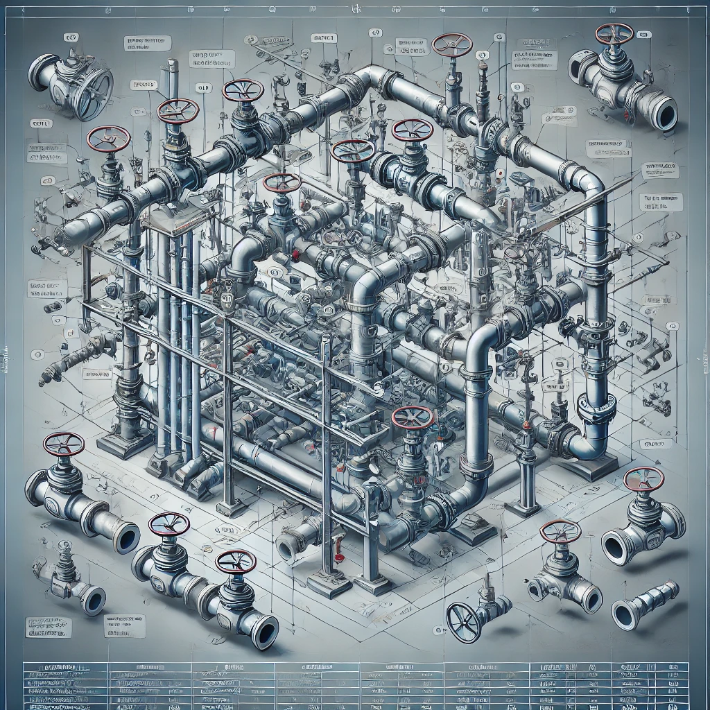
Pipe isometric drawings are a form of graphical representation that depicts a piping system in a three-dimensional view. Unlike orthographic drawings, which show views from specific angles (front, side, top), isometric drawings combine these perspectives to offer a more comprehensive view. This makes it easier to understand the spatial relationships between different parts of the piping system.
In an isometric drawing, the pipes are typically drawn along three axes (X, Y, and Z), which are inclined at 30 degrees to the horizontal plane. This inclination gives the viewer a pseudo-3D perspective, making it possible to visualize the layout as it would appear in the real world. The primary purpose of these drawings is to provide clear and concise information about the piping system, including dimensions, material specifications, and the positioning of components such as valves, flanges, and fittings.
Importance of Pipe Isometric Drawings
Pipe isometric drawings play a critical role in the engineering and construction of piping systems for several reasons:
- Clarity and Precision: These drawings provide a clear and accurate depiction of complex piping systems, which is essential for avoiding errors during fabrication and installation.
- Communication: They serve as a universal language between engineers, designers, fabricators, and contractors, ensuring that all parties have a consistent understanding of the piping system.
- Material Takeoff: Isometric drawings are used to determine the quantity of materials required for a project, including the length of pipes, number of fittings, and other components.
- Installation Guide: They act as a blueprint for the installation team, guiding them on how to assemble the piping system on-site.
- Maintenance and Modifications: These drawings are also valuable for future maintenance, repairs, and modifications, providing a reference to the original design.
Key Components of Pipe Isometric Drawings
A well-prepared pipe isometric drawing includes several essential components that collectively provide a complete understanding of the piping system. These components are:
- Piping Route and Orientation:
- The drawing clearly indicates the route and orientation of the pipes, including any changes in direction.
- Pipes are represented by single lines, with elbows, tees, and other fittings shown at appropriate junctions.
- Dimensions and Scale:
- Isometric drawings typically include dimensions such as length, width, and height, which are essential for accurate fabrication and installation.
- While these drawings are not to scale, they provide the actual dimensions of pipes and components.
- Pipe Size and Specifications:
- The drawing should specify the pipe size (diameter), material, and wall thickness, which are crucial for selecting the appropriate pipe for the application.
- This information is often noted alongside the pipe route in the drawing.
- Component Symbols:
- Various symbols are used to represent different components such as valves, flanges, reducers, and fittings. Understanding these symbols is essential for interpreting the drawing accurately.
- Each symbol follows a standardized format as per industry guidelines (e.g., ANSI/ASME standards).
- Weld and Joint Information:
- The drawing should indicate the location of welds and joints, which is critical for the fabrication and assembly process.
- Information about the type of joint (e.g., butt weld, socket weld) may also be provided.
- Support and Hanger Details:
- Isometric drawings may include information about pipe supports and hangers, ensuring that the piping system is properly supported and secured.
- The type, location, and spacing of supports are typically detailed in these drawings.
- Bill of Materials (BOM):
- A BOM is often included with isometric drawings, listing all the materials and components required for the piping system.
- This includes the quantity, size, material grade, and other specifications for each item.
- Flow Direction:
- The drawing should indicate the direction of flow within the piping system, which is critical for understanding how the system operates.
Creating Pipe Isometric Drawings: Best Practices
Creating accurate and effective pipe isometric drawings requires attention to detail and adherence to industry standards. Here are some best practices to follow:
- Adherence to Standards:
- Follow industry standards such as ANSI/ASME, ISO, or DIN when preparing isometric drawings. These standards provide guidelines for symbols, dimensions, and notations.
- Use of Software Tools:
- Modern CAD software such as AutoCAD, SmartPlant, and PDMS offer specialized tools for creating pipe isometric drawings. These tools automate many aspects of the drawing process, improving accuracy and efficiency.
- Clarity and Simplicity:
- Ensure that the drawing is clear and easy to interpret. Avoid clutter by only including necessary details and using a consistent layout.
- Cross-Referencing:
- Cross-reference isometric drawings with other related documents such as P&IDs (Piping and Instrumentation Diagrams) and orthographic drawings to ensure consistency and completeness.
- Dimensioning:
- Provide accurate dimensions for all elements in the drawing. Double-check dimensions to avoid errors during fabrication and installation.
- Component Labeling:
- Label all components clearly and consistently. Use standard abbreviations and symbols to avoid confusion.
- Review and Verification:
- Review the drawing thoroughly before finalizing it. Engage in a review process that includes checking for errors, verifying dimensions, and ensuring that all components are accurately represented.
- Continuous Learning:
- Stay updated with the latest industry standards, software tools, and best practices in piping design and isometric drawing.
Interpreting Pipe Isometric Drawings
Interpreting pipe isometric drawings requires familiarity with the symbols, notations, and conventions used in these drawings. Here are key points to consider when reading and interpreting these drawings:
- Understand the Axes:
- Recognize that the pipes are represented along the X, Y, and Z axes. Visualize how these axes translate to the actual piping layout on-site.
- Identify Flow Direction:
- Look for arrows or other indicators that show the direction of flow within the piping system.
- Check Dimensions:
- Pay close attention to the dimensions provided. Ensure that they match the physical space available for installation.
- Read the BOM:
- Refer to the Bill of Materials for details on the components required. Cross-check the BOM with the drawing to ensure all components are accounted for.
- Consult Other Documents:
- Use isometric drawings in conjunction with other design documents like P&IDs and general arrangement drawings to get a complete understanding of the system.
Conclusion
Pipe isometric drawings are indispensable tools in the design, construction, and maintenance of piping systems. Their ability to provide a detailed and accurate three-dimensional representation of piping layouts makes them essential for engineers, designers, fabricators, and contractors. By adhering to best practices in creating and interpreting these drawings, professionals can ensure that piping systems are designed, installed, and maintained efficiently and effectively, minimizing errors and optimizing performance. As industries continue to evolve, the role of pipe isometric drawings will remain central to successful piping projects.