To conduct the calculation, you will need the following parameters:
| STEP 1: Pipe Properties and design Parameter | ||
| Parameter | Source | Note |
| Design Life | BFD | |
| Fluid category | BFD | |
| NPS | BFD | |
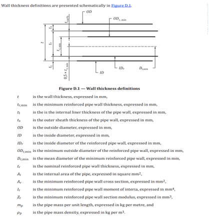
| ID | BFD | |
| DP | BFD | |
| DT | BFD | |
| Installation temperature | Per Country | |
| Qualified stress | By Manufacturer | |
| STEP 2: Part factors for loading and partial factors | ||
| Parameter | Source | Note |
| f1 | ASTM D2992 | |
| f2 | By Manufacturer | f2=0.67 for above ground, f2=0.89 for hydrotest |
| f3 | By Manufacturer | f3=0.85 for above ground, f3=1 for buried |
| A1 | ISO 14692-3 | |
| A2 | ISO 14692-3 | A2 shall be 1 |
| A3 | ISO 14692-3 | The minimum value for A3 is 0.25 |
| Liner thickness | By Manufacturer | |
| Topcoat thickness | By Manufacturer | |
Calculation Methodology:
| STEP 1: Qualified stress for non-standard design (if not provided by vendor) | |||
| No. | Parameter | Formula | Note |
| 1 | | G= Appropriate gradient of the regression line, T= Non-standard design life for qualified stress (Number of years) | |
| 2 | Lower confidence limit | | Qualified stress (in MPa) times 10 |
| 3 | Percentage of reduction | | |
| 4 | Qualified stress | in MPa | |
| STEP 2: Reinforced wall thickness Calculation | |||
| No. | Parameter | Formula | Note |
| 1 | Required reinforced wall thickness | | |
| 2 | Nominal wall thickness | ||
| 3 | Mean diameter | ||
| 4 | Hoop stress |  | |
| 5 | Factored stress | in MPa | |
| 6 | Maximum hoop stress | in MPa | |
| 7 | Collapse pressure | Fe = 3 (Long term), Fe = 1.5 (Short term) | |
| STEP 3: Wall thickness buoyancy check | |||
| No. | Parameter | Formula | Note |
| 1 | Weight of pipe | in N/m | |
| 2 | Weight of soil | in N/m | |
| 3 | Total downward forces |  | in N/m |
| 4 | Upward forces | in N/m | |