What do we mean by pipeline Tie-In?
The term ‘Tie-in’ typically refers to connecting a pipeline to a facility, another pipeline or piping system, or joining different sections of a pipeline or piping. Additionally, Tie-ins encompass additions or modifications made to existing systems.
Tie-in welds are defined as welded joints that cannot be performed during the main front-end welding or production phase of the main pipeline laying. These welds are necessary at joints that were not welded by the initial front-end welding crew. The efficiency and cost-effectiveness of the main pipeline production depend on the continuous progress and optimal use of the front-line crew and equipment. Therefore, any interruptions to this continuous process must be minimized. Some joints require tie-in welds because they were physically inaccessible at the time, while others involve non-standard or awkward joints that would excessively delay the main production if attempted earlier.
Tie In Process – Joint Alignment
The process begins by aligning the two pipe ends using side booms, with additional dressing carried out if necessary to achieve the correct weld gap. An external centralising clamp is then applied to ensure concentric alignment and correct any ovality between the pipe ends. Ovality tolerances typically apply only to pipe ends, not along the length of the pipe, so cutting joints mid-length can lead to unexpected ovality.
Next, steel wedges are used to adjust the gap between the pipes, ensuring it remains parallel around the entire circumference of the weld. However, the use of external clamps like these presents a challenge to employing automated welding equipment. The completion time for these operations can vary depending on crew skill and alignment requirements, potentially taking up to 2 hours to finish.
Tie In for On-Plot Facilities
Typically, in all pipeline projects, the Tie-in location and configuration are determined during the initial studies by both the Process and Pipeline/Mechanical groups, aligning with project requirements and defined battery limits. Consequently, the Pipeline/Mechanical group prepares a Tie-in index drawing based on the Process Engineering Flow Scheme (PEFS) issued by the Process group.
A standard Tie-in index drawing includes essential information such as the tie-in location, configuration of the tie-in joint, dimensions, and material specifications for existing and new hardware (whether piping or pipeline), as well as any shutdown requirements. This drawing serves as a comprehensive reference detailing the specifics needed to execute the tie-in effectively within the project’s operational and safety parameters.
Tie-In Methods
- Mecahnical Tie-in
- A ‘Tie-in’ involving a planned shutdown of operating facilities or pipeline systems necessitates a partial shutdown aligned with production targets and forecasts set by the operations group. The mechanical tie-in can be achieved either through new flanged pipe spools with bolting or by welding directly to the existing system. Each method is selected based on project requirements, operational considerations, and safety protocols to ensure seamless integration and minimal disruption during the tie-in process.
- Hot-Tap Tie-in
- A ‘Tie-in’ without shutting down operating facilities or pipeline systems involves a Hot Tap method, which utilizes special pipe fittings like Split-Tees, Weldolets, Reinforcement pads, Full encirclement sleeves, etc. This approach allows for making connections to piping or other equipment by attaching a fitting to the system, typically through welding. Subsequently, a hot-tapping machine cuts through the pipe wall at the attachment point, enabling the connection to be made while the system remains live, without decommissioning or interrupting flow.
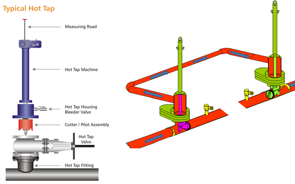
What is Hot Tapping?
Hot tapping is a method of making new connections to the piping system by attaching a fitting to the system usually by welding followed by cutting through the pipe wall at the point of attachment utilizing an appropriate (hot tapping) machine.
Uses:
- In situ maintenance
- Replacement and repairs
- Tie ins
- Future provisions
Hot Tapping Procedure
After the tapping fitting is securely attached to the existing pipe, the tapping valve is bolted onto the outlet of the fitting to ensure a pressure-tight connection. A special adapter allows the tapping machine to bolt onto the tapping valve outlet, also creating a pressure-tight seal. Once the tapping valve is opened, the cutter pilot drill assembly is inserted through the valve and guided to the nozzle until it makes contact with the outside of the existing pipe.
With the tapping machine’s automatic feed engaged and power supplied, rotation begins, and the pilot drill starts penetrating the side of the pipe. As soon as the penetration is achieved, the fitting, valve, and tapping machine adapter fill with the fluid inside the pipe. If this fluid is combustible, it’s standard procedure to open a bleed in the adapter to purge any air from the components. The bleed valve is closed once the product begins to appear, and the cutting process continues.
The tapping process is completed when the shell cutter not only severs the coupon but also continues its travel into the existing pipe, ensuring the cut reaches its proper diameter sometime after the coupon is fully separated. To prevent the coupon from falling into the pipeline, a mechanism on the pilot drill typically retains it. By retracting the boring bar on the tapping machine, the cutter, pilot drill, and coupon return into the tapping machine adapter. At this point, the gate of the tapping valve can be closed.
With the tapping machine removed, access to the interior of the pipeline is achieved without interrupting the line’s service. This method allows for maintenance or modifications to be conducted while the pipeline remains operational.