What are the energy considerations that must be taken into accout in pipeline engineering?
Energy considerations in pipeline engineering are central pillars in the discipline and include the following:
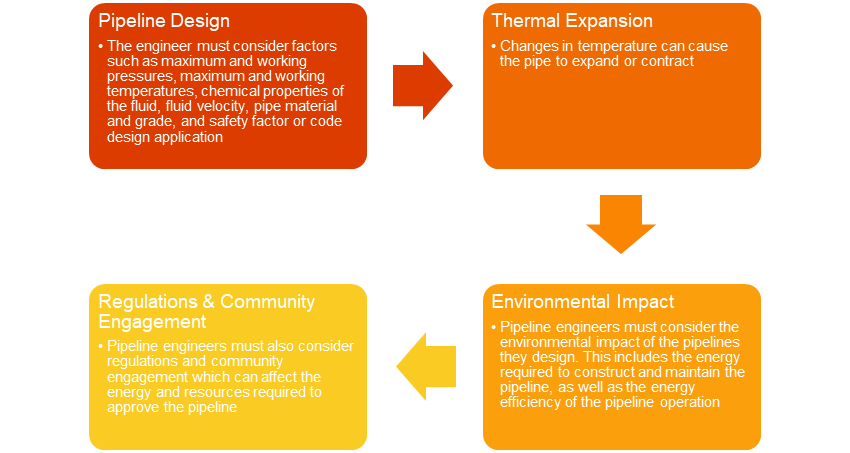
- Pipeline Design
- The engineer must consider factors such as maximum and working pressures, maximum and working temperatures, chemical properties of the fluid, fluid velocity, pipe material and grade, and safety factor or code design application.
- Thermal Expansion
- Changes in temperature can cause the pipe to expand or contract.
- Regulations and community engagement
- Pipeline engineers must also consider regulations and community engagement which can affect the energy and resources required to approve the pipeline.
- Environmental Impact
- Pipeline engineers must consider the environmental impact of the pipelines they design. This includes the energy required to construct and maintain the pipeline, as well as the energy efficiency of the pipeline operation.
What are system curves?
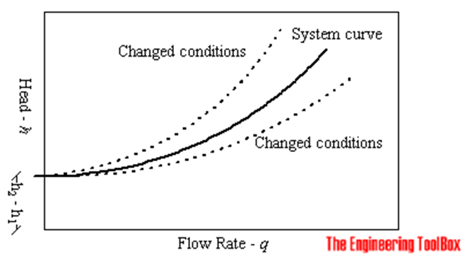
- A fluid flow system is characterized with the System Curve
- A system curve is a plot of the head or pressure required to move a fluid through a system of pipes, fittings, vessels, or other equipment.
The system curve is a function of elevation and the major and minor losses in the system which can be measured as follow:
h = dh + hl (1)
where
- h = system head (m)
- dh = h2 – h1 = elevation (static) head difference between the inlet and outlet in the system (m)
- hl = major and minor head loss in the system (m)
hl = k q2 (2)
where
- q = flow rate
- k = constant describing the total system characteristics – including all major and minor losses
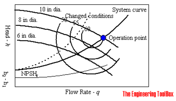
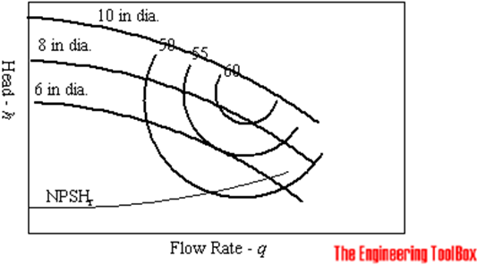
- System curve is combined with pump curves to select the proper pump.
- Pump curves describes the relation between the flowrate and the head of the actual pump.
- Increasing the impeller diameter or speed increases the head and flow rate capacity.
- The head capacity can be increased by connecting two or more pumps in series.
- the flow rate capacity can be increased by connecting two or more pumps in parallel.
- The optimal pump is selected based on the best operating conditions as the above graph.
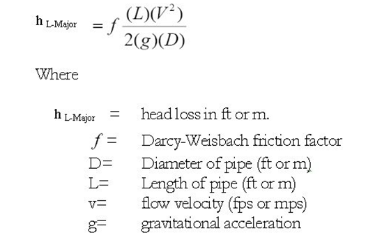
What are Head Loss calculations?
- Head loss in a pipeline refers to the reduction in the total head pressure of a fluid as it flows through a pipe.
- Head loss is caused by friction, turbulence, and other factors that result in energy loss.
- When fluid flows inside a pipeline, friction occurs between the moving fluid and the stationary pipe wall.
- The friction converts some of the fluid’s hydraulic energy into thermal energy.
- The thermal energy cannot be converted back to hydraulic energy, so the pressure drops.
- Head loss is proportional to the length of the pipe, the square of the fluid velocity and the friction factor, and inversely pro proportional to the diameter of the pipe.
What is the concept of equivalent length?
- Equivalent length is used to describe the pressure drop through a fitting as a length of the pipe.
- Theoretically, the pressure drop through the fitting is equivalent to the pressure lost through a certain length of the pipeline at that corresponding flow rate.
- Major losses are proportional to the velocity head (V^2)/2g
- The L/D method simply increases the multiplying factor in the Darcy-Weisbach equation by a length of a straight pipe.
- This in turn would give rise to a pressure loss equivalent to the losses in the fittings, hence the name equivalent length.
- All fittings, elbows, tees, can be summed up to make one total length, and the pressure loss calculated from this length.
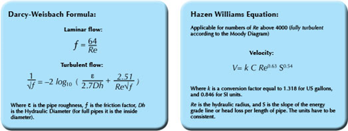
What do we mean by pipe roughness?
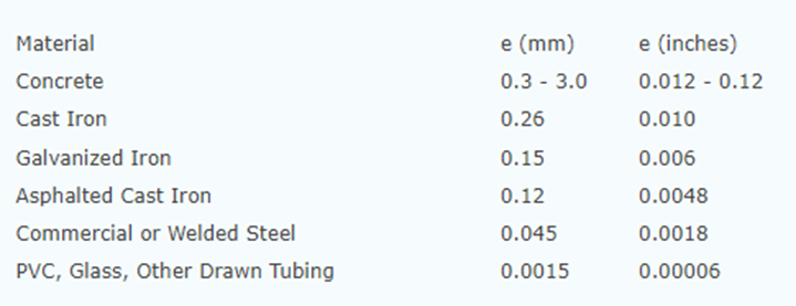
- The internal roughness of a pipe is an important factor when considering the friction losses of a fluid moving through the pipe.
- For each pipe material either a single pipe roughness value or a range of values is normally provided by the manufacturer
- The roughness value is used in the calculation of the relative roughness of a pipe against the size of its diameter.
- The roughness of a pipe is normally denoted as e and is provided in either mm or inches.
- The relative roughness of pipe is its roughness divided by its internal diameter or e/D
- The relative roughness value is then used in the calculation of the pipe friction factor which is then used to calculate the head loss of a flowing pipe.
What is NPSH?
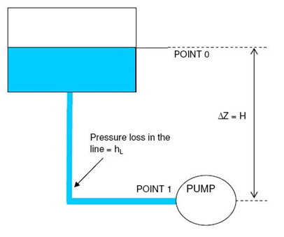
- NPSH stands for Net Positive Suction Head which is a measurement used to determine the ability of a pump to handle liquid without cavitation.
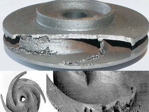
- Cavitation for pumps is a condition within the impeller eye where the pressure falls below the liquid vapor pressure and the liquid boils.
- NPSH for pumps can be defined as the difference between liquid pressure at the pump suction and liquid vapor pressure, expressed in terms of the height of the liquid column.
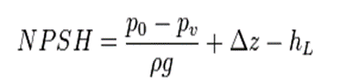
- hL is the head loss between 0 and 1
- p0 is the pressure at the water surface
- pV is the vapour pressure (saturation pressure) for the fluid at the temperature T1 at 1
- Δz is the difference in height z1 − z0
- ρ is the fluid density
- g is gravitational acceleration
- If the available NPSH at the pump suction is less than the required.
- head (NPSHr), there is a risk of the formation of vapor bubbles at
- the pump suction.
- Presence of vapor in the pump suction leads to several problems such.
- as cavitation, damage to impellers, dry running of pump.
- NPSHr is normally provided by the pump manufacturer.
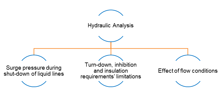
What is a hydraulic analysis schematic and work plan?
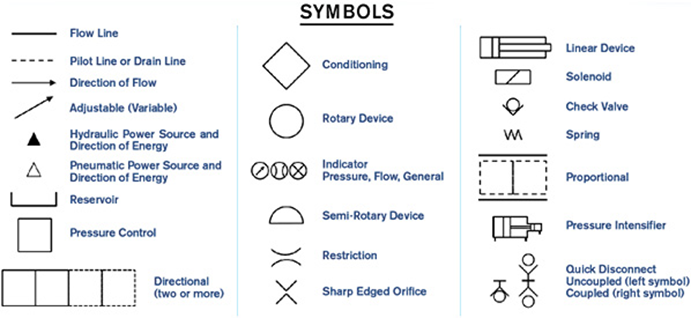
- A hydraulic circuit is a system comprising an interconnected set of discrete components that transport liquid.
- This system may be to control where fluid flows or to control fluid pressure.
- The hydraulic analysis shall provide data to address the following:
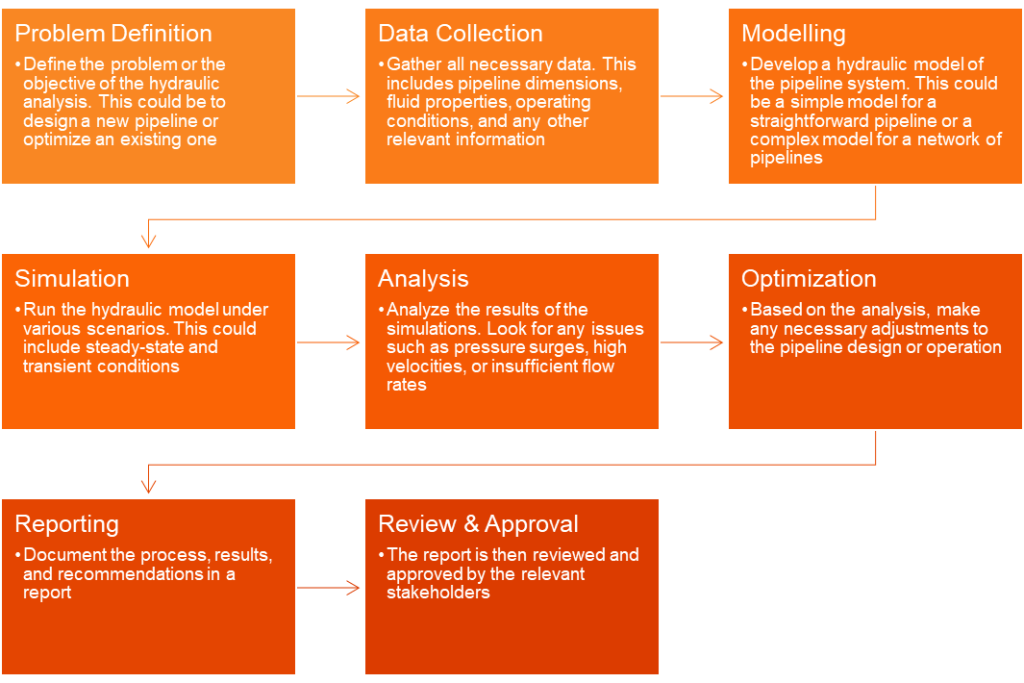
- A work plan to conduct a hydraulic analysis in pipeline engineering typically involves the following steps:
Which software is used for hydraulic moodeling in pipeline engineering?
| Software | Application |
| PIPESIM | Hydraulic sizing |
| TLNET | Single-phase liquids/ to assess the impact of new pipeline designs and tie-ins to existing pipeline system |
| TGNET | Single-phase gases/ to assess the impact of new pipeline designs and tie-ins to existing pipeline system |
| OLGA | Multiphase pipelines/ to provide transient analysis |