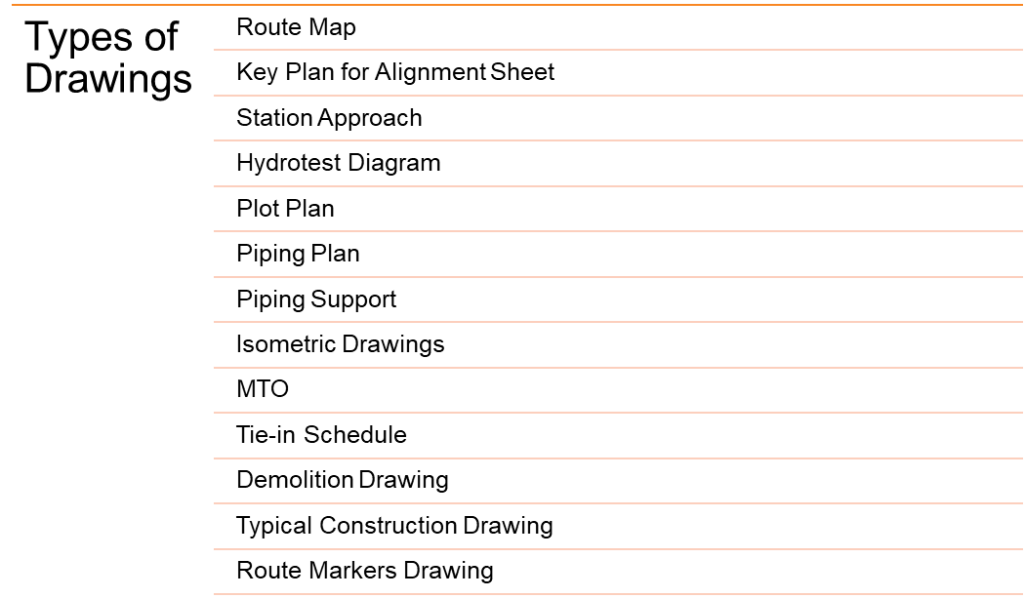
What are the different types of drawings used in pipeline engineering?

Route Maps
- They are used to establish the pipeline route, avoid populated areas, forests, and mining areas, keep the number of crossings to a minimum, and ensure easy approachability to the Right of Way (ROW)
- Presenting the proposed route for new Pipeline along with their associated facilities at Off-Plot/On-Plot areas
- Main components:
- Drawing limits
- Notes
- List of abbreviations
- Legends
- Record existing facilities (crossings pipeline, third party pipelines, cable, Flowline, OHL, wells …etc.).
Plot Plans
- A schematic representation of the entire site, including boundaries, roads, buildings, plant areas, equipment layouts, utility runs, and other constructions of the existing project, all at a properly defined scale.
- The plot plan contains all the components by designated numbers and shows to scale, the basic shape of the equipment and supporting facilities, locating them in both the vertical and the horizontal planes.
- Usually initiated in the pre-contract, conceptual, and development stages of a proposal and is developed with proper information and dimensions during the detailed engineering phase as the project progresses.
- A Plot plan provides the following information:
- Total area details of the process plant
- The exact location of equipment, buildings, roads, etc.
- The total number of equipment to be erected in the plot
- Length of a pipe rack
- Area of each individual unit
Alignment Sheets
- They graphically show the exact route and location of the pipeline and associated facilities.
- Alignment sheets are done in DD and are only for buried pipelines.
- All the knowledge that exists for a pipeline when it is being designed is captured in these sheets.
- Alignment sheets contain:
- Grade elevation
- Slope chainage
- As-built chainage
- Design factor
- Pipe wall thickness
- Crossing details
- Terrain surface / rock profile
- Pearson survey
- Fiber optic cable joints
- Coatings
- Minimum Cover
- Markers
- As-built data
Station Approach Layout Drawings
- A specific type of technical drawing used to detail the design and layout of a pipeline as it approaches a station.
- A station refers to a specific location along the pipeline where certain operations or functionalities are housed, such as pump stations, valve stations, or metering stations.
- These drawings provide a detailed view of the pipeline’s path as it approaches and enters the station, including:
- The layout of the pipeline
- The location and type of fittings and valves
- The connection points.
- Station Approach drawings are crucial for the construction, operation, and maintenance of the pipeline.
Hydrostatic Test Diagram
- Preparation of hydrotest diagram:
- Dividing T/L, P/L, or F/L into appropriate test sections (based on code requirements, test pressure limitations)
- Hydrotest pressure calculations (considering elevations)
- 10 m of water column=0.98 bars pressure
- Flange test pressures for different ratings
- ISO 15590
- Line pipe test pressures based on 90% SMYS.
- Any other weakest components
- Installation of valves before or after tests
- Golden weld concept
- Test duration
- Road crossing, A/G & B/G sections
- It contains:
- Grade elevations in meters
- Hydrostatic Test Schedule
- Hydrotested pipeline setup such as the scraper receiver and launcher
Piping GAD’s/Piping Plan
- Piping plans show all major equipment and their relative orientations as well as all piping leading to and from equipment.
- All main piping items (valves, fittings, etc.), instrumentation, access ladders, and platforms are shown.
- The piping plan usually shows a top view with elevations and sectional drawings with piping dimensions and details such as line numbers, size, specifications, and the direction of flow.
- A piping plan drawing provides the following necessary information:
- Pipe routing, length, and coordinates
- Spacing or centreline distance between one pipe to the other line
- Correct positioning of the piping assembly on the pipe rack
- Type of pipe supports required in the piping and pipeline systems.
- Instrument connection to the piping
- Equipment connection
Tie-in Schedule
- The term tie-in is generally used to describe the connection of a pipeline to a facility to other pipeline systems or the connecting of different sections of a single pipeline.
- Tie-in schedule provides an organized method of presenting general notes or lists of materials, building components, equipment, and so forth in a drawing in tabulated form.
Isometrics
- It is a method of graphic representation of three-dimensional objects.
- Isometric drawings are a good way to show measurements and how components fit together.
- Isometric drawings represent the pipe routing with proper dimensions including all piping items and equipment.
- These drawings are not to scale and show single line diagrams with symbols for pipeline components, weld points, and supports.
Material Take-off – MTO
- MTOs enlists tables for the materials for fabrication and material for erection
- The tables highlight the quantity, MR/MESC No., Class, Size, and description
- MTOs are made following the below steps:
- Scope of material selection:
- PEFS, piping class verification, overall route map, crossing matrix, and station approach documents are received
- MTO (Material Take Off) is issued to procurement
- Checking and organizing items with SAP and MESC numbers
- Prepare MTO based on PEFS and pipeline drawings
- Scope of material selection:
- Checking and issue for use


