In first, you have to understand that pipeline engineering is an extensive field that is comprised of design, construction, and maintenance and overlaps with many other functions such as electrical, civil, piping, mechanical, and process. However, with a solid background in mechanical engineering, the candidate can expect the following questions in a graduate pipeline engineer job interview.
Can you tell us about material classification?
This is a general question to investigate your material science background and can be answered accordingly:
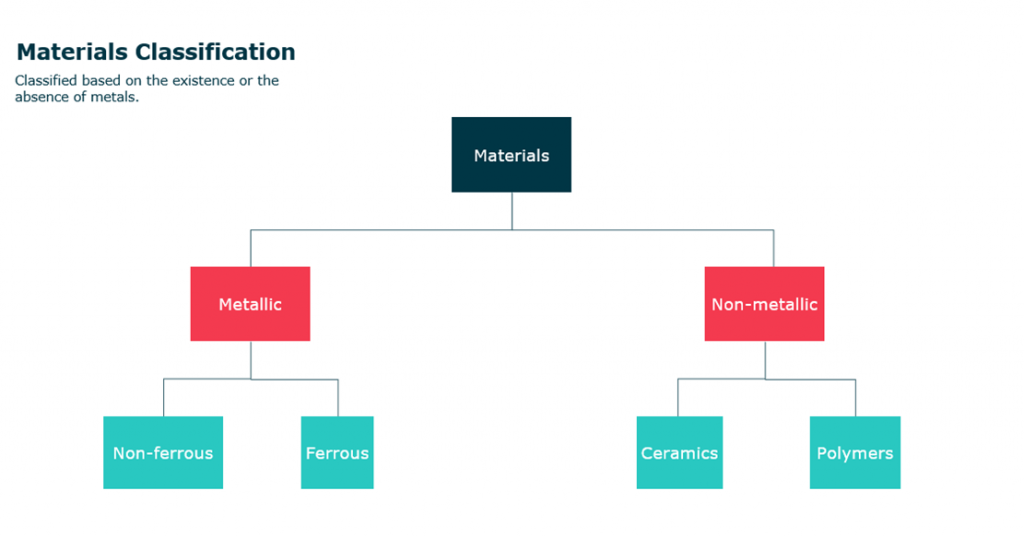
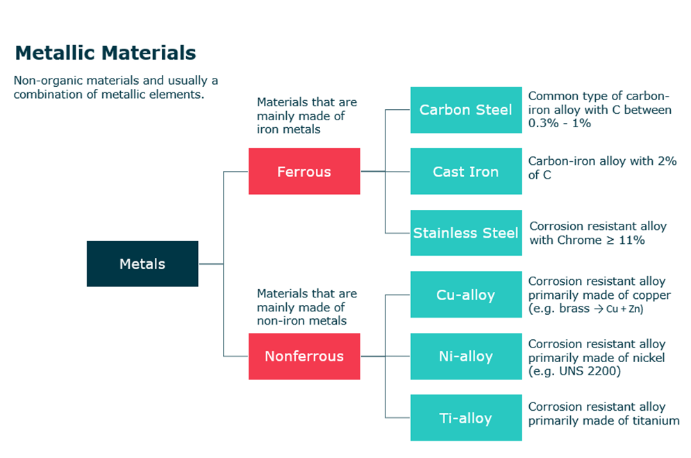
Materials commonly are classified based on the existence or absence of metals into Metallic materials and non-metallic materials.
First, metallic materials are non-organic materials and are usually a combination of metallic elements (e.g. Fe, Ti, Al, Ag). This category is subsequently divided into two types which are ferrous and non-ferrous materials.
- Ferrous materials:
- Materials that are mainly made of iron metal
- Examples:
- Carbon steel: common type of carbon iron alloy with min 0.3% C and max. 1% C
- Cast Iron: Carbon-iron alloy with 2% of C
- Stainless Steel: Corrosion resistance alloy with CR<= 11%
- Non Ferrous materials:
- Materials that are made of non-iron metals
- Examples:
- Cu-alloy: Corrosion resistance alloy primary made of copper (e.g. brass = Cu + Zn)
- Ni-alloy: Corrosion resistance alloy primary made of nickel (e.g. UNS 2200)
- Ti-alloy: Corrosion resistance alloy primary made of titanium
The second type of materials is nonmetallic materials. This class can be
- Polymers
- Class of a natural/ synthetic substance compound made of very large molecules. The following are examples of nonmetallic materials.
- Ceramics
- Non-metallic, non-organic, and non-reactive materials with hard, brittle, heat resistance, and corrosion resistance properties.
What are material properties and explain each property?
Material properties are dependent on three factors:
- Mechanical work
- Heat treatment
- Chemical composition
We manipulate these factors to achieve the desired material properties.
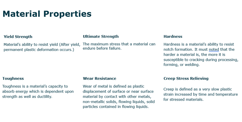
- Yield strength: Material’s ability to resist yield (after yield, permanent plastic deformation occurs).
- Ultimate strength: The maximum stress that a material can endure before failure.
- Fracture: Material Failure.
- Hardness: Material’s resistance to notch formation, however, the harder the material, the more susceptible to cracking during processing, forming, or welding. Hardness test methods:
- Brinell method
- Rockwell methods
- Vickers method
- Toughness: A material’s capacity to absorb energy, which is dependent upon strength as well as ductility. Toughness test methods:
- Charpy V notch: Most applicable method
- Drop weight nil ductility: Used for brittle materials.
- Crack tip opening displacement: Used for measuring flaw size.
- Wear resistance: Plastic displacement of surface or near surface material by contact with other metals, nonmetallic solids, flowing liquids, solid particles contained in flowing liquids.
- Creep stress relieving: Creep is defined as a very slow plastic strain increased by time and temperature for stressed materials.
- Rupture: A materials failure due to creep.
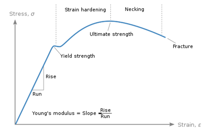
What is Stress Vs. Strain curve and how to draw it?
Stress Vs Strain curve is a graphical representation of the relationship between stress and strain in a given material. We know that stress is equivalent to the force applied to a material per unit area and is measured in MPa, N/mm2, bar, .etc. The curve contains two zones which are the elastic and plastic. In first, the material exhibits an elastic deformation where it can return to its original shape once the applied force is lifted. This region continues until the yielding point. Yielding signifies a material’s ability to resist plastic deformation which is the second area. Beyond yielding point, the material’s deformation is permanent and can never return to its original shape. In first, strain hardening occurs where the material distributes the stress throughout the tested specimen until the ultimate tensile stress. Beyond UTS, necking region occurs where the material’s deformation localizes in specific areas eventually leading to fracture.
What do you know about Carbon Steel, Stainless Steel, Duplex Stainless Steel, and Super Duplex Stainless Steel?
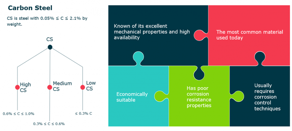
Carbon Steel
- CS is steel with 0.05% ≤ C ≤ 2.1% by weight.
- Known of its excellent mechanical properties and high availability.
- Economically suitable.
- The most common material used today.
- Usually requires corrosion control techniques.
- Has poor corrosion resistance properties.
- CS types:
- Low carbon steel: <= 0.3% carbon
- Medium carbon steel: 0.3% < C <= 0.6%
- High carbon steel: 0.6% < C <= 1%
Stainless Steel
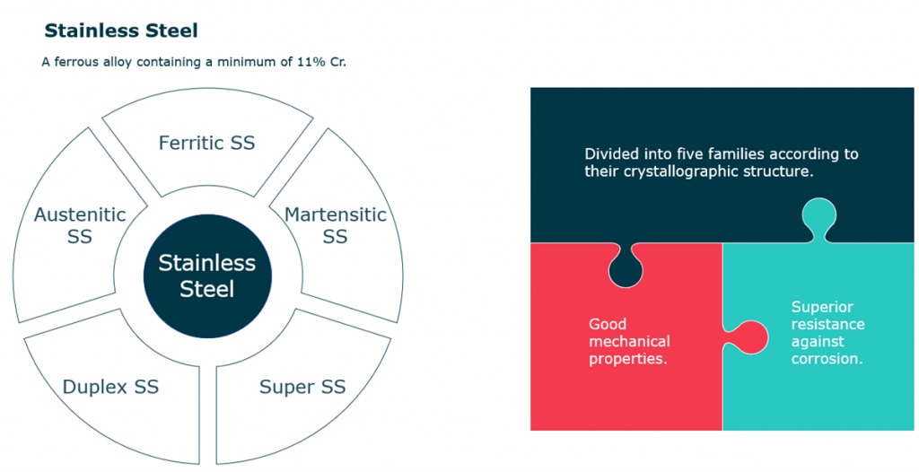
- Stainless steel is defined as a ferrous alloy containing a minimum of 11% of Cr.
- Known of its superior resistance against corrosion.
- Known of its good mechanical properties.
- Divided into five families according to their crystallographic structure.
- SS families:
- Austenitic SS.
- Ferritic SS.
- Martensitic SS.
- Super SS.
- DSS
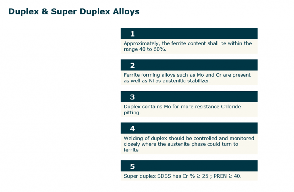
Duplex & Super Duplex Stainless Steel
- Approximately the ferrite content shall be within the range 40 to 60 %.
- Duplex contains Mo for more resistance Chloride pitting.
- Ferrite forming alloys such as Mo and Cr are present as well as Ni as austenitic stabilizer.
- Welding of duplex should be controlled and monitored closely where the austenite phase could turn to ferrite.
- Super duplex SDSS has CR % 25; PREN (Pitting resistance equivalent number) ≥40.
What do you know about equilibrium phase diagrams?
A phase diagram in its essence is a visual representation of the stable states of a material or mixture under specific conditions. There are two two types of phase diagrams which are the binary phase diagram for carbon-iron system and the Ternary phase diagram for Fe-Cr-Ni system. We are mainly interested in the binary system.
The binary system:
The following equation shows the eutectic reaction for the iron-iron carbide system that occurs at 4.3 wt% C and 1147 degrees Celsius.
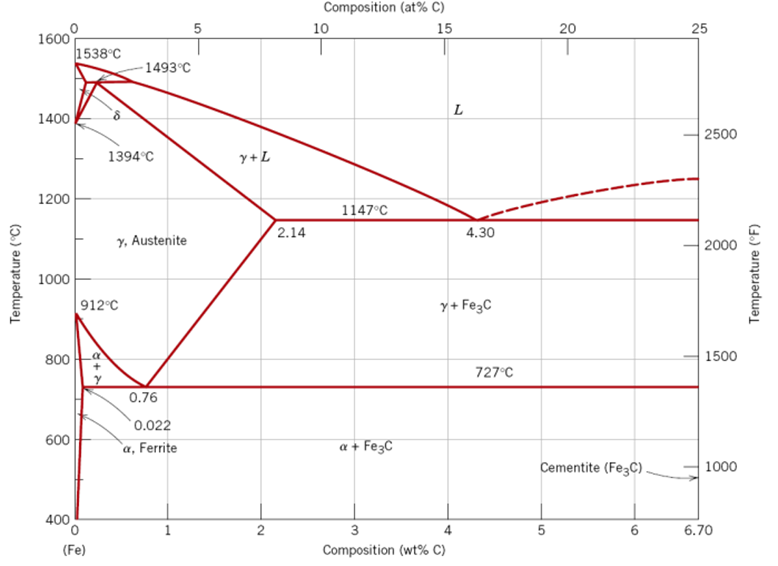
The L means liquid phase and Fe3C means cementite. The liquid solidifies to make austenite and cementite phases.
L –> γ + Fe3C
At 0.78% carbon and 727 degrees Celsius, appoint called eutectoid invariant exists and is represented by the following:
γ (0.76%) <–>α (0.022 %C) + Fe3C (6.7 %C)
- α – Iron
- Also called ferrite, a stable form of BCC structure between 1400 -1539 degrees Celsius.
- δ – Iron
- Same as the previous, however, with low-to-non engineering interest.
- γ – Iron
- Austenite is a solid solution of mostly iron and carbon. Austenite only forms when an iron-based alloy is heated above 750 degrees Celsius, but less than 1450 degrees Celsius.
- Cementite
- Also called Fe3C, which is represented by a vertical line in the phase diagram. Thus, the carbon-iron system is divided into two categories:
- Iron-rich: With carbon content of <= 6.7%.
- Iron-poor: Made of pure graphite ≈ 100% C.
- Also called Fe3C, which is represented by a vertical line in the phase diagram. Thus, the carbon-iron system is divided into two categories:
- Pearlite
- Pearlite is a mixture of ferrite and cementite forming distinct layers or bands in slowly cooled carbon steels.
- Martensite
- A very hard form of steel crystalline structure, and it is produced by quenching γ – Iron
Ternary Phase Diagram for Fe-Cr-Ni System
A ternary phase diagram shows possible phases and their equilibrium according to the composition of a mixture of three components (Fe-Cr-Ni) at constant temperature and pressure.
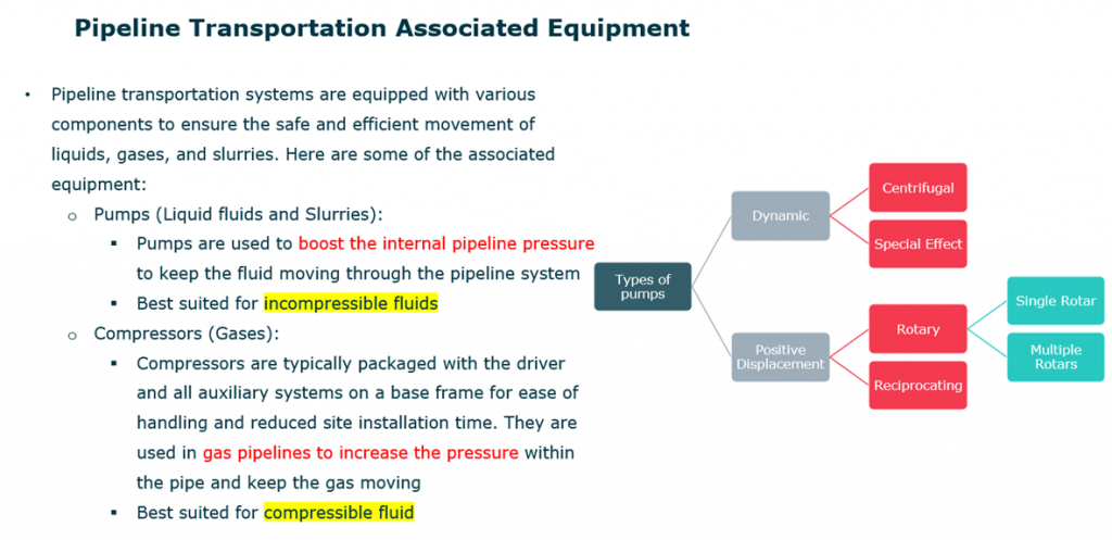
What do you know about pipeline transportation systems?
Pipeline transportation systems are equipped with various components to ensure the safe and efficient movement of liquids, gases, and slurries. Here are some of the associated equipment:
- Pumps (Liquid fluids and Slurries):
- Pumps are used to boost the internal pipeline pressure to keep the fluid moving through the pipeline system.
- Best suited for in-compressible fluids
- Compressors (Gases):
- Compressors are typically packaged with the driver and all auxiliary systems on a base frame for ease of handling and reduced site installation time. They are used in gas pipelines to increase the pressure within the pipe and keep the gas moving.
- Best suited for compressible fluid
What are the various types of valves?
- Gate Valve
- Gate valves, commonly encountered in process plants, utilize a linearly moving gate to control fluid flow by either blocking or allowing it. These valves offer effective shutoff and are suitable for a wide range of fluid services, including air, fuel gas, feedwater, steam, slurries, and viscous liquids.
- Globe Valve
- Globe valves typically feature a spherical body housing a movable plug element and a stationary ring seat. The body is divided into two halves by an internal baffle. A stem connects the plug element to an operating hand wheel. By turning the wheel, the plug moves toward or away from the ring seat, allowing for fluid flow regulation. Globe valves serve both stop/start functions and precise flow control. They find applications in systems where leak tightness and effective flow management are critical, such as cooling water systems, feedwater systems, chemical feed systems, and fuel/lubricating oil systems.
- Ball Valve
- A ball valve employs a hollow ball to control fluid flow. By pivoting the perforated ball using the valve handle, the fluid can either flow through or be blocked. When the hole in the ball aligns with the flow inlet, fluid passes; a quarter-turn (90°) rotation of the handle blocks the flow.
- Butterfly Valve
- The “butterfly” refers to a rotatable metal disc mounted on a rod. A quarter turn of the disc is required to open or shut-off the valve. In the closed position, the disk completely blocks off the passageway. In the open position, the face of the disc is parallel to the flow direction and allows nearly unrestricted fluid flow. Butterfly valves find applications in cooling water systems, compressed air or gas applications, fire protection, slurry services, vacuum service, and high-pressure / high-temperature water and steam services.
- Needle Valve
- Needle valves share a design resemblance with globe valves. These valves feature a long, tapered, needle-like plunger that fits into a matching seat to halt fluid flow. By turning the stem, the plunger is either inserted or retracted, thus opening or restricting the flow path. The finely threaded stem requires multiple turns to fully retract the plunger, allowing precise flow rate regulation. Needle valves find common use in small-diameter piping systems where fine flow control is essential. They are suitable for low-viscosity fluids at low flow rates. A primary application is regulating flow to delicate gauges, safeguarding them from damage due to sudden pressure surges. Additionally, needle valves serve as bleed valves for pressure relief or fluid drainage during analysis or maintenance.