
Introduction
Pipeline hydraulic sizing is a critical process in the design and engineering of pipeline systems. Proper hydraulic sizing ensures that the pipeline operates efficiently, safely, and reliably by optimizing the flow of fluids—whether liquids, gases, or multi-phase mixtures—through the pipeline. The hydraulic sizing of a pipeline involves determining the appropriate pipe diameter, wall thickness, and material, as well as calculating pressure drops, flow rates, and other key factors. This article provides a comprehensive guide to the principles and calculations involved in pipeline hydraulic sizing, covering the essential concepts, formulas, and best practices.
Understanding Pipeline Hydraulic Sizing
Pipeline hydraulic sizing refers to the process of determining the most suitable pipe size (diameter) and related parameters to ensure that a fluid can be transported through a pipeline efficiently and with minimal losses. This involves balancing several factors, including flow rate, pressure, fluid properties, and the physical characteristics of the pipeline. Proper hydraulic sizing is crucial for:
- Minimizing Pressure Drops: Ensuring that the pressure loss along the pipeline is within acceptable limits, which is critical for maintaining adequate flow and avoiding excessive energy consumption.
- Optimizing Flow Velocity: Maintaining an appropriate flow velocity to prevent issues such as erosion, corrosion, and fluid degradation.
- Ensuring Structural Integrity: Choosing the correct pipe diameter and wall thickness to withstand internal pressures and external loads.
- Reducing Operating Costs: Selecting an optimal pipe size can lead to significant savings in pumping energy and material costs.
Key Parameters in Pipeline Hydraulic Sizing
Several key parameters must be considered when performing hydraulic sizing calculations:
- Flow Rate (Q):
- The flow rate is the volume or mass of fluid passing through a pipeline per unit time. It is typically measured in cubic meters per second (m³/s) or liters per second (L/s) for liquids, and standard cubic meters per hour (Sm³/h) or kilograms per hour (kg/h) for gases.
- Fluid Properties:
- Density (ρ): The mass per unit volume of the fluid, usually expressed in kilograms per cubic meter (kg/m³). Density affects the pressure drop and the energy required to transport the fluid.
- Viscosity (μ): The fluid’s resistance to flow, measured in pascal-seconds (Pa·s) or centipoise (cP). Viscosity influences the frictional losses in the pipeline.
- Compressibility: For gases, the compressibility factor (Z) accounts for deviations from ideal gas behavior, which affects the pipeline’s pressure and flow characteristics.
- Pipe Diameter (D):
- The internal diameter of the pipe is a crucial factor in determining the flow rate, velocity, and pressure drop. Larger diameters generally reduce pressure drops but may increase material and installation costs.
- Pipe Length (L):
- The total length of the pipeline affects the overall pressure drop due to friction. Longer pipelines typically require higher pumping power or greater pressure at the inlet.
- Pressure Drop (ΔP):
- The reduction in pressure from the pipeline’s inlet to its outlet, primarily due to friction, elevation changes, and fittings. Managing pressure drop is critical for efficient pipeline operation.
- Flow Velocity (v):
- The speed at which the fluid travels through the pipeline. The flow velocity must be optimized to avoid problems like erosion or inadequate flow.
Key Equations for Hydraulic Sizing
Several fundamental equations are used in hydraulic sizing calculations. Below are the most commonly used equations:
- Continuity Equation:
- The continuity equation expresses the conservation of mass in the pipeline: Q=A×vQ = A \times vQ=A×v Where:
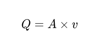
- Q = flow rate (m³/s)
- A = cross-sectional area of the pipe (m²)
- v = flow velocity (m/s)
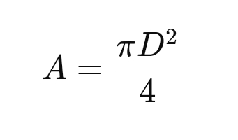
- For a circular pipe, the area A can be calculated as:
- Darcy-Weisbach Equation:
- This equation is used to calculate the pressure drop due to friction in a pipeline:
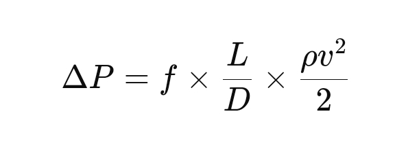
- Where:
- ΔP = pressure drop (Pa)
- f = Darcy friction factor (dimensionless)
- L = length of the pipeline (m)
- D = internal diameter of the pipe (m)
- ρ = fluid density (kg/m³)
- v = flow velocity (m/s)
- Reynolds Number (Re):
- The Reynolds number is a dimensionless quantity used to predict flow regimes (laminar or turbulent):
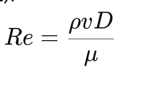
- Where:
- Re = Reynolds number (dimensionless)
- μ = dynamic viscosity of the fluid (Pa·s)
- Fanning Friction Factor (f):
- The friction factor f in the Darcy-Weisbach equation can be determined from the Moody chart or using empirical correlations based on the Reynolds number and pipe roughness.
- Bernoulli’s Equation:
- Bernoulli’s equation relates the pressure, velocity, and elevation in a flowing fluid:
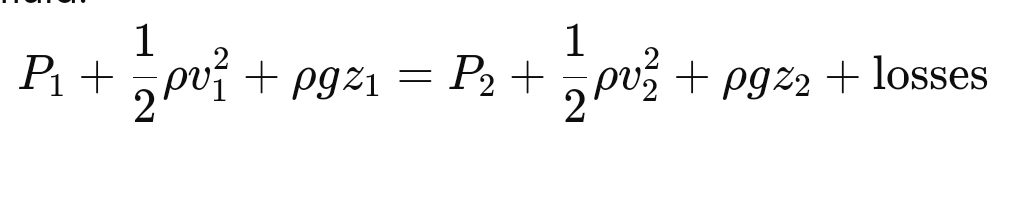
- Where:
- P1,P2 = pressure at points 1 and 2 (Pa)
- v1,v2 = flow velocity at points 1 and 2 (m/s)
- z1,z2 = elevation at points 1 and 2 (m)
- losses = head loss due to friction and fittings
Steps for Performing Pipeline Hydraulic Sizing Calculations
- Determine Fluid Properties:
- Gather the necessary data on fluid properties, including density, viscosity, and compressibility. This information is often available from process data sheets or fluid property databases.
- Calculate Required Flow Rate:
- Define the desired flow rate based on process requirements. This could be specified in terms of mass or volumetric flow rates.
- Select Initial Pipe Diameter:
- Choose an initial pipe diameter based on industry standards, past experience, or guidelines. This diameter will be refined through subsequent calculations.
- Calculate Flow Velocity:
- Use the continuity equation to calculate the flow velocity for the chosen pipe diameter. Ensure the velocity is within acceptable limits for the fluid and application.
- Estimate Pressure Drop:
- Apply the Darcy-Weisbach equation to calculate the pressure drop along the pipeline. Include losses due to friction, fittings, and elevation changes.
- Check Reynolds Number:
- Calculate the Reynolds number to determine the flow regime. Use the appropriate correlation or the Moody chart to find the friction factor.
- Refine Pipe Diameter:
- If the calculated pressure drop or flow velocity is not within acceptable limits, adjust the pipe diameter and repeat the calculations until an optimal size is determined.
- Consider Safety and Design Margins:
- Apply safety factors or design margins to account for uncertainties, future expansions, or variations in operating conditions.
- Validate Against Standards:
- Ensure the final pipeline design complies with relevant industry standards (e.g., ASME, API) and regulatory requirements.
Best Practices in Pipeline Hydraulic Sizing
- Start with Accurate Data:
- Ensure that fluid properties and process requirements are accurate and up-to-date. Errors in input data can lead to incorrect sizing and potential operational issues.
- Use Software Tools:
- Leverage hydraulic modeling software (e.g., AFT Fathom, PIPE-FLO, Aspen HYSYS) to automate calculations and simulate complex systems. These tools can help optimize designs and reduce the risk of errors.
- Consider Future Operations:
- Design pipelines with future expansions, changes in fluid properties, or varying operational conditions in mind. This can prevent costly modifications later.
- Document Assumptions:
- Keep a detailed record of all assumptions, calculations, and design decisions. This documentation is essential for reviews, audits, and future reference.
- Consult with Experts:
- Engage with experienced engineers or consultants when dealing with complex fluids, high pressures, or unusual conditions. Expert input can help avoid pitfalls and ensure a robust design.
Conclusion
Pipeline hydraulic sizing is a critical component of pipeline design that impacts the efficiency, safety, and cost-effectiveness of a project. By carefully considering flow rates, fluid properties, pipe diameter, and pressure drops, engineers can design pipelines that meet operational requirements and minimize risks. Following best practices and using advanced tools can further enhance the accuracy and reliability of hydraulic sizing calculations, ensuring successful pipeline operations.