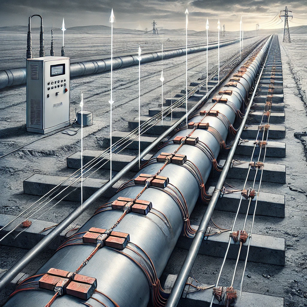
Cathodic protection (CP) is a vital technique used in pipeline engineering to prevent corrosion, extending the life of pipelines and ensuring their structural integrity. Corrosion, a natural electrochemical process, occurs when a metal pipeline is exposed to an electrolyte, such as soil or water, leading to the deterioration of the metal. Cathodic protection mitigates this process by making the pipeline the cathode of an electrochemical cell, thereby halting the corrosion reaction. This article delves into the two primary methods of cathodic protection—sacrificial anode and impressed current systems—and provides an overview of how to calculate the requirements for each.
Basics of Cathodic Protection
In an electrochemical cell, the anode is where oxidation (corrosion) occurs, and the cathode is where reduction happens. By controlling this reaction, cathodic protection effectively reduces the corrosion rate of the metal pipeline by converting it into the cathode, where no oxidation (corrosion) occurs.
Sacrificial Anode Cathodic Protection (SACP)
Overview
Sacrificial anode cathodic protection (SACP) involves attaching a more reactive metal (the sacrificial anode) to the pipeline. Common materials for sacrificial anodes include magnesium, zinc, and aluminum. These metals are chosen because they have a more negative electrode potential compared to steel, meaning they will corrode preferentially, protecting the pipeline.
Calculation of Sacrificial Anode Requirements
The design of an SACP system involves calculating the number of sacrificial anodes required to protect the pipeline over its expected life. The key steps include:
- Determine the Current Requirement: The current requirement III to protect the pipeline is calculated using the equation:
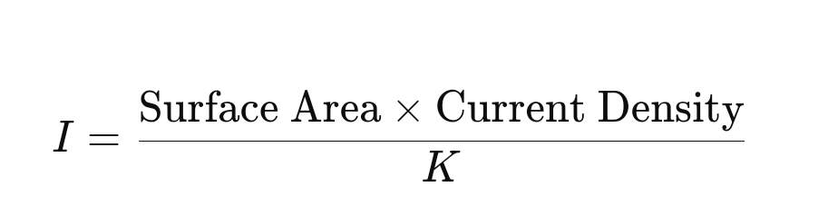
- Surface Area: The total surface area of the pipeline to be protected.
- Current Density: The amount of current required per unit area to achieve protection, typically ranging from 1 to 3 mA/m² for pipelines.
- K: A factor to account for coating quality, typically between 0.5 and 1.
- Anode Capacity: The capacity of the anode material (A) is based on its consumption rate, typically given in ampere-hours per kilogram (Ah/kg). For example, the theoretical capacity of magnesium is about 2200 Ah/kg.
- Number of Anodes: The number of anodes NNN required is calculated using:
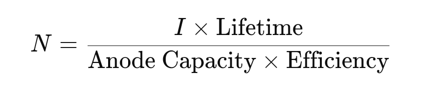
- Lifetime: The desired protection period, typically in years.
- Efficiency: The efficiency of the anode, accounting for practical losses, usually around 0.85.
This calculation provides the total number of anodes needed to protect the pipeline for the intended duration. The anodes are strategically placed along the pipeline to ensure uniform protection.
Impressed Current Cathodic Protection (ICCP)
Overview
In impressed current cathodic protection (ICCP), an external power source is used to drive a protective current through the pipeline, making it the cathode. Unlike SACP, ICCP does not rely on the natural corrosion of the anode material to generate the protective current. Instead, an inert anode, typically made of materials like titanium or mixed metal oxide (MMO), is connected to a DC power supply.
Calculation of Impressed Current Requirements
Designing an ICCP system involves determining the amount of current required and the design of the anode bed:
- Current Requirement: Similar to SACP, the current requirement III for ICCP is calculated based on the surface area of the pipeline and the required current density. However, in ICCP systems, this current is supplied by an external DC power source, allowing for greater flexibility and control.
- Anode Bed Design: The anode bed is a critical component of an ICCP system. It consists of several anodes buried in the ground (groundbed), connected to the positive terminal of the power source. The key considerations in anode bed design include:
- Anode Material: Selection based on durability, current carrying capacity, and cost. Common materials include graphite, MMO, and platinum-coated titanium.
- Anode Spacing and Layout: The anodes must be spaced to ensure even distribution of the protective current along the pipeline. The layout is often linear or distributed, depending on the pipeline’s length and the surrounding environment.
- Power Supply Calculation: The total power required for the ICCP system is determined by:
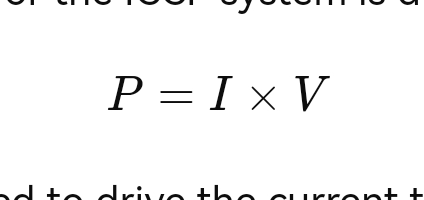
- V: The voltage required to drive the current through the system. This includes the voltage drop across the anode bed, cables, and pipeline coating.
- Voltage Drop Considerations: The system design must account for voltage drops along the pipeline, particularly in long-distance pipelines. These drops can reduce the effectiveness of the protection at the farthest points from the power source.
Comparison of SACP and ICCP
While both SACP and ICCP aim to prevent pipeline corrosion, they have different advantages and applications:
- SACP:
- Simpler and lower cost, particularly for smaller pipelines or where external power is not readily available.
- Limited by the availability of suitable anode materials and the need for regular maintenance and replacement of anodes.
- ICCP:
- Provides greater control over the protection current, making it suitable for larger or more complex pipeline systems.
- Higher initial cost and complexity due to the need for power sources and more sophisticated system design.
Conclusion
Cathodic protection is a critical component of pipeline corrosion prevention strategies, with both sacrificial anode and impressed current systems offering reliable protection under various conditions. Understanding the principles and calculations behind these systems allows engineers to design effective CP solutions tailored to specific pipeline environments, ensuring the longevity and safety of these essential infrastructure components. Whether using the simplicity of sacrificial anode systems or the precision of impressed current systems, the goal remains the same: to protect pipelines from the relentless threat of corrosion.