Definition
The design and construction of a pipeline involves the process of dividing the line into different segments by using block valve stations. Also known as sectionalizing valve stations, these stations allow the sections to be isolated for inspection, maintenance, and emergency. As a definition, a block valve is a valve used for interrupting the flow or to shut in a section of a pipeline. A block valve is normally fully opened or fully closed. A block valve can almost be any valve type in the widest sense. All that is required of the valve is that it prevents motion in at least one direction part of time. Because that word refers to any valve, there is a temptation to restrict it down to a more specific classification.
Purpose
BVS purpose is as follow:
- Minimize loss of product in the event of a pipeline failure
- To facilitate repairs
- Facilitate operational flexibility in a looped pipeline system.
The valve must accomplish two things with a more restricted meaning. When the valve is open, it must not affect the flow of the substance. It must completely prohibit material from goring through the valve when it is closed. The block valve is typically a full-bore, soft seated ball valve to allow for pigging, a practice that includes cleaning and inspecting the pipeline. However, it is not recommended that soft seated ball valves be opened against full differential pressure as damage to the valve seats can occur. To mitigate valve seat damage, a bypass system is installed around the main block valve to balance the pipeline pressure prior to opening. For these bypass requirements, plug valves are commonly used because their inherent design tolerates full differential pressure and allows for the opening and throttling without damage.
BVS Components:
Pipework
- Bypass line:
- Minimum diameter should be sized in line with velocity limitations.
- The design shall take due account of the following:
- Avoidance of hydrates
- Acceptable noise levels
- Possibility of future connections with pump stations
- Excessive vibration during pigging
- Oil lines:
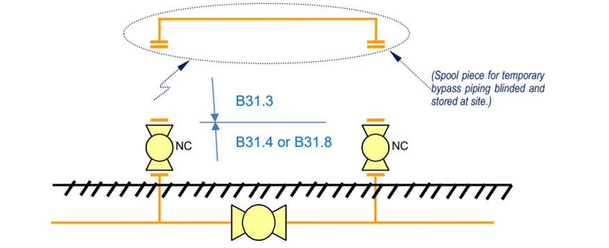
- Bypass line shall not be installed permanently for liquid lines as dead legs would occur.
- Adequately protect externally & internally
- Gas lines:
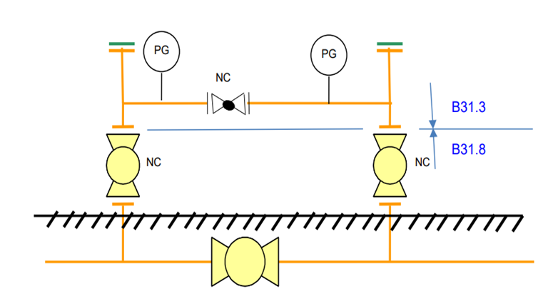
- Bypass can be installed, and bypass valves should be normally closed
- Drain line:
- Liquid lines without automated BVS: Drain points should not be provided.
- Liquid lines with automated BVS: Drain points shall be provided.
- Gas lines: Drain points should not be provided.
- Flare/Vent line:
- Vent connections shall be provided on the bypass lines to blow down intermediate sections.
Valves
- For toxic services, block valves and bypass valves shall be welded into the pipeline.
- For non-toxic services, the valves should have flanged ends.
- When valves are flanged, bolts shall be tightened in a controlled manner using hydraulic bolt tensioning equipment.
- Mainline Isolation Valves:
- It shall be full bore ball valve to allow pigging of the line.
- Mainline isolation valve should not be welded type.
- Check Valves:
- Check valves shall not be used for BVS.
- Bypass valves:
- It shall be full bore valve.
- These valves will be in closed position with a blind installed.
- Throttle Valve for gas lines only:
- It shall a globe or suitable control valve depending on the size.
- The valve is installed for flow control during pressurization of a pipeline section.
- Relief Valves:
- It shall be installed where the shut in pressure could exceed the design pressure because of thermal expansion of static fluid.
- Thermal relief may be required for liquid lines with an automated BVS and bypass permanently in place.
- Thermal relief is not required for liquid lines with manual BVS, and bypass is not permanently installed
Branch Connections
- Diameter of all branch connections shall be at least 2”
- The connection of bypass lines to mainline shall always be piggable tees
Other Components
- Pressure Indicator Connections:
- Should not be installed on manually operated BVS for liquid lines.
- Should be installed on the bypass line to enable above ground installation for automated BVS.
- Temperature Indicator:
- Not required
- Gas lines shall be designed for the lowest temperature during depressurizing.
- Pig Signallers:
- Intrusive pig signallers shall not be installed on a BVS.
- Space for non-intrusive type shall be provided for installation.
- Supports:
- Shall be designed to carry the weight of above ground section of the bypass line filled with water.
- Shall be electrically isolated from aboveground piping
Layout
- BVS shall have at least two gates on opposite sides
- One gate shall be for light vehicle access.
- The other gate is to provide an alternative emergency escape route for personnel.
- Fixed area lighting is not required.
Location
- Each BVS requires a study to determine the location based on the following:
- Spacing requirements
- Elevation differences and hydrostatic head
- Terrain features
- Leak sizes
- Time needed until reaching a BVS.
- Convenient access from black top/graded roads, as well as access to mains electrical supplies
- Possibility of interference from a third party
- BVS shall be away from existing facilities at a distance based on risk assessment
BVS Spacing:
A minimum number of BVSs is the ideal design approach. The spacing between a BVS and another is a function of location class in accordance with ASME B31.8. The following highlights the spacing requirements based on location class:
(1) 20 mi (32 km) in areas of predominantly Location Class 1
(2) 15 mi (24 km) in areas of predominantly Location Class 2
(3) 10 mi (16 km) in areas of predominantly Location Class 3
(4) 5 mi (8 km) in areas of predominantly Location Class 4
The spacing defined herein may be adjusted to permit a valve to be installed in a location that is more accessible.
Design Guidelines:
Design Code
- BVS including aboveground pipework shall be designed according to the same code as the pipeline which are based on the fluid category as per ASME B31.4/ B31.8
- The piping beyond the bypass valves may be designed to B31.3
Design Factor
- For pipelines with a hoop stress design factor higher than 0.6, the BVS shall be designed with a design factor of 0.6 to increase safety margins.
- For pipelines with a factor less than 0.6, BVS shall be designed with an equal factor to that pipeline.
Design Pressure
- BVS design pressure shall be equal to that of the pipeline.
Design Temperature
- For aboveground pipework at BVS, the max. and min. temperatures shall be the same as that of the pipeline’s pig traps.
- Max. and min. design temperature for buried pipeline within BVS shall be the same as that of tor buried pipeline outside the BVS.
- Calculations shall be made for operating temperatures in the bypass line due to throttling or during depressurisation for gas lines.
Design Velocities
- Acceptable maximum velocities are 8 m/s in case of oil and 40 m/s in case of gas.